|
Electronic circuits and components * Course Index * Introduction * About the Author * About this Course * Feedback * Course Navigation * How to use this Course * TINA * Locktronics Fundamentals * Introduction: Fundamentals * Units and Multiples * Electricity * Electronic Principles * Electrical Circuits * Alternating Current * Assessment: Fundamentals Passive Components * Introduction: Passive Components * Resistors * Capacitors * Inductors ## Inductor Specifications ## Preferred Values: Inductors ## Inductor Markings ## Examples: Inductor Markings ## Inductor Symbols ## Inductor Construction ## Inductors in Series ## Inductors in Parallel ## Examples: Inductors in Circuits ## Variable Inductors * Transformers * Batteries, Fuses, Lamps and Switches * Assessment: Passive Components Semiconductors * Introduction: Semiconductors * Diodes * Transistors * Logic Gates * Assessment: Semiconductors Passive Circuits * Introduction: Passive Circuits * Series and Parallel Connections * Kirchoff's Laws * Potential and Current Dividers * Passive Time Variant Circuits * Assessment: Passive Circuits Active Circuits * Introduction: Active Circuits * Power Supply Circuits * Operational Amplifier Circuits * Transistor Amplifier Circuits * 555 Timer Circuits * Assessment: Active Circuits Parts Gallery * Introduction: Parts Gallery * Passive Component Images * Semiconductor Images * Other Images * Quizzes |
(:Summary:Contains the 'action' links (like Browse, Edit, History, etc.), placed at the top of the page, see site page actions:) (:comment This page can be somewhat complex to figure out the first time you see it. Its contents are documented at PmWiki.SitePageActions if you need help. :) * Print (:comment (:if group Site,SiteAdmin,Cookbook,Profiles,PmWiki*:) (:comment delete if and ifend to enable backlinks:) * %item rel=nofollow class=backlinks accesskey='$[ak_backlinks]'% [[{*$Name}?action=search&q=link={*$FullName} | $[Backlinks] ]] (:ifend:) :) * Login Inductor Markings<^< Preferred Values: Inductors | Course Index | Examples: Inductor Markings >^>(:nl:) 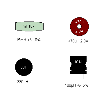 As with capacitors, the vast majority of inductors use written markings to indicate values, working current, and tolerance. The most usual method of marking ferrite cored inductors involves quoting the value (in mH or μH), the tolerance (often either 5% or 10%), and the maximum working current (where appropriate). The marking scheme follows a similar convention to that used with small capacitors: First line: Inductance (in mH or μH) and tolerance (J=5%, K=10%, M=20%). Second line: rated d.c. current (where specified). A three-digit code is often used to mark small inductors. The first two digits correspond to the first two digits of the value whilst the third digit is a multiplier which gives the number of zeros to be added to give the value in μH. Some small inductors are marked with coloured stripes to indicate their value and tolerance (the standard colour values are used and inductance is normally expressed in μH). (:nl:)(:table style="clear:both":)
| |
(:Summary: Website page footer:)
Print - (:comment (:if group Site,SiteAdmin,Cookbook,Profiles,PmWiki*:) (:comment delete if and ifend to enable backlinks:) %item rel=nofollow class=backlinks accesskey='$[ak_backlinks]'% [[{*$Name}?action=search&q=link={*$FullName} | $[Backlinks] ]] (:ifend:) :) Search - Login
Page last modified on July 21, 2011, at 02:53 PM