|
Electronic circuits and components * Course Index * Introduction * About the Author * About this Course * Feedback * Course Navigation * How to use this Course * TINA * Locktronics Fundamentals * Introduction: Fundamentals * Units and Multiples * Electricity * Electronic Principles * Electrical Circuits * Alternating Current * Assessment: Fundamentals Passive Components * Introduction: Passive Components * Resistors * Capacitors * Inductors * Transformers * Batteries, Fuses, Lamps and Switches * Assessment: Passive Components Semiconductors * Introduction: Semiconductors * Diodes * Transistors * Logic Gates ## AND Switch ## OR Switch ## Buffers ## Inverters ## AND Gates ## OR Gates ## NAND Gates ## NOR Gates ## Exclusive-OR Gates ## Exclusive-NOR Gates * Assessment: Semiconductors Passive Circuits * Introduction: Passive Circuits * Series and Parallel Connections * Kirchoff's Laws * Potential and Current Dividers * Passive Time Variant Circuits * Assessment: Passive Circuits Active Circuits * Introduction: Active Circuits * Power Supply Circuits * Operational Amplifier Circuits * Transistor Amplifier Circuits * 555 Timer Circuits * Assessment: Active Circuits Parts Gallery * Introduction: Parts Gallery * Passive Component Images * Semiconductor Images * Other Images * Quizzes |
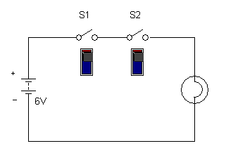
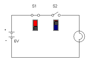
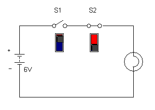
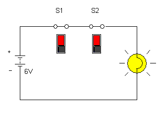
(:Summary:Contains the 'action' links (like Browse, Edit, History, etc.), placed at the top of the page, see site page actions:) (:comment This page can be somewhat complex to figure out the first time you see it. Its contents are documented at PmWiki.SitePageActions if you need help. :) * Print (:comment (:if group Site,SiteAdmin,Cookbook,Profiles,PmWiki*:) (:comment delete if and ifend to enable backlinks:) * %item rel=nofollow class=backlinks accesskey='$[ak_backlinks]'% [[{*$Name}?action=search&q=link={*$FullName} | $[Backlinks] ]] (:ifend:) :) * Login AND Switch<^< Logic Gates | Course Index | OR Switch >^>(:nl:) The operation of a simple AND gate can be illustrated by connecting two switches in series with a battery and a lamp. It should be obvious that the lamp will only operate when both switches (S1 AND S2) are closed. Furthermore, since each switch can only be in one of the two states (i.e., open or closed) at any given time, the open and closed conditions are mutually exclusive. Furthermore, since a switch cannot exist in any other state than completely open or completely closed (i.e., there is no intermediate or half-open state) the circuit is based on binary or 'two-state' logic.
| |
(:Summary: Website page footer:)
Print - (:comment (:if group Site,SiteAdmin,Cookbook,Profiles,PmWiki*:) (:comment delete if and ifend to enable backlinks:) %item rel=nofollow class=backlinks accesskey='$[ak_backlinks]'% [[{*$Name}?action=search&q=link={*$FullName} | $[Backlinks] ]] (:ifend:) :) Search - Login
Page last modified on July 22, 2011, at 02:17 PM