|
Electronic circuits and components * Course Index * Introduction * About the Author * About this Course * Feedback * Course Navigation * How to use this Course * TINA * Locktronics Fundamentals * Introduction: Fundamentals * Units and Multiples * Electricity * Electronic Principles * Electrical Circuits * Alternating Current * Assessment: Fundamentals Passive Components * Introduction: Passive Components * Resistors * Capacitors * Inductors * Transformers * Batteries, Fuses, Lamps and Switches * Assessment: Passive Components Semiconductors * Introduction: Semiconductors * Diodes * Transistors * Logic Gates ## AND Switch ## OR Switch ## Buffers ## Inverters ## AND Gates ## OR Gates ## NAND Gates ## NOR Gates ## Exclusive-OR Gates ## Exclusive-NOR Gates * Assessment: Semiconductors Passive Circuits * Introduction: Passive Circuits * Series and Parallel Connections * Kirchoff's Laws * Potential and Current Dividers * Passive Time Variant Circuits * Assessment: Passive Circuits Active Circuits * Introduction: Active Circuits * Power Supply Circuits * Operational Amplifier Circuits * Transistor Amplifier Circuits * 555 Timer Circuits * Assessment: Active Circuits Parts Gallery * Introduction: Parts Gallery * Passive Component Images * Semiconductor Images * Other Images * Quizzes |
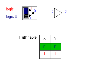
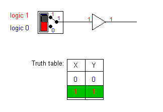
(:Summary:Contains the 'action' links (like Browse, Edit, History, etc.), placed at the top of the page, see site page actions:) (:comment This page can be somewhat complex to figure out the first time you see it. Its contents are documented at PmWiki.SitePageActions if you need help. :) * Print (:comment (:if group Site,SiteAdmin,Cookbook,Profiles,PmWiki*:) (:comment delete if and ifend to enable backlinks:) * %item rel=nofollow class=backlinks accesskey='$[ak_backlinks]'% [[{*$Name}?action=search&q=link={*$FullName} | $[Backlinks] ]] (:ifend:) :) * Login Buffers<^< OR Switch | Course Index | Inverters >^>(:nl:) Buffers do not affect the logical state of a digital signal, i.e., a logic 1 input results in a logic 1 output whereas a logic 0 input results in a logic 0 output. Buffers are normally used to provide extra current drive at the output but can also be used to regularize the logic levels present at an interface. The Boolean expression for the output, Y, of a buffer with an input, X, is: Y = X Note:- the response of a gate or circuit to an input, or set of inputs, can be expressed in a number of ways. One of the most simple and most intuitive methods is the truth table shown here where the logic for any given input, X, is shown at the output, Y. The algebraic system used to express the relationship between inputs and outputs in a circuit is called 'Boolean logic'.
| |
(:Summary: Website page footer:)
Print - (:comment (:if group Site,SiteAdmin,Cookbook,Profiles,PmWiki*:) (:comment delete if and ifend to enable backlinks:) %item rel=nofollow class=backlinks accesskey='$[ak_backlinks]'% [[{*$Name}?action=search&q=link={*$FullName} | $[Backlinks] ]] (:ifend:) :) Search - Login
Page last modified on July 22, 2011, at 02:29 PM