The Lab 10 exercises were written for a PIC16F1937 processor with LEDs connected to Port B, and an analogue light dependent resistor (LDR) sensor connected to analogue pin 0.
Setting up the analogue port on the V3 Development board
We are going to use the on-board light dependent resistor (LDR) connected to an analogue pin AN0. To make this connection you must move the top jumper on the J14 links to connect the analogue sensor correctly. You can refer to the development board documentation to find out more.
Matrix E-blocks users
The Lab 10 exercises require an EB004 LED board connected to Port B, and an EB003 Sensors board connected to Port A.
An example layout is shown opposite.
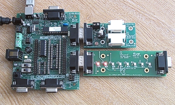
E-blocks setup for Lab 10
Version 3 Development board Analogue selector block