If a program on your PC goes wrong the operating system will usually detect this before the computer crashes. If a program on a PIC microcontroller goes wrong there is no operating system to step in and sort things out. To get around this the PIC microcontroller provides a "watchdog" timer. This is driven from a separate clock (i.e. not the main PIC microcontroller's clock) and works in the same way as TIMER0, in that when it overflows it can cause an event. In the case of the watchdog it will cause the PIC microcontroller to be reset or woken up from sleep (of which more later).
The idea is that when your program is running normally it will regularly reset the watchdog timer. There is a special PIC microcontroller instruction to do this, BoostC provides a function called clear_wdt:
/* reset the watchdog timer */
clear_wdt () ;
If your program crashes it will stop resetting the watchdog, which will overflow and cause a reset - forcing the program to restart. Status bits in the PIC microcontroller can be used to detect that a reset has been caused by a watchdog overflow and so your program can know that it just fell over and hopefully do something about it.
The watchdog timer time-out is normally 18 milliseconds or around a 56th of a second. It is not possible to be precise about these figures because the clock circuitry on the PIC microcontroller used to drive the watchdog is not as stable as a crystal. This means that if your program crashes and stops resetting the watchdog it will be reset within around 18 milliseconds of the crash occurring.
It might be that you don't want the watchdog to step in quite as quickly as that. If this is the case you can use a pre-scaler on the watchdog in just the same way that we can prescale TIMER0. Unfortunately this process also uses the same pre-scaler, which means that you can pre-scale the watchdog, or the timer, but not both.
The watchdog pre-scaler range runs from 1 to 128, meaning that the longest time-out you can have is 18 millisecond * 128 - or about 2.3 seconds.
If the PIC microcontroller is in sleep mode (of which more later) when the watchdog triggers it will continue execution from the instruction after the sleep instruction. If you are feeling cunning you can use the watchdog timer to make a system which uses very low power and wakes up every now and then to check or do something.
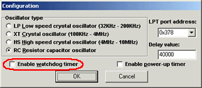
If you want to use the watchdog you have to set one of the configuration bits to turn the watchdog hardware on. It is important that you set this bit correctly, if the watchdog is Accidentally switched on in a PICmicro you will find that your program spontaneously resets every now and then.

You can control the settings of the of the configuration bits from PPP. If you select the Watchdog tick box the watchdog timer is enabled for the PIC microcontroller and your program must perform regular clear_wdt actions to avoid being reset.
OPTION - OPTION Control register
|
Bit 7 |
Bit 6 |
Bit 5 |
Bit 4 |
Bit 3 |
Bit 2 |
Bit 1 |
Bit 0 |
|
!RBPU |
INTDG |
T0CS |
T0SE |
PSA |
PS2 |
PS1 |
PS0 |
Items in red are not relevant to the watchdog.
PSA - PreScaler Assignment Bit
If this bit is set the prescaler is assigned to the watchdog. This means that TIMER0 will be updated at the instruction clock rate.
The pre-scaler lets you control the rate at which the timer counts. It divides the timer input frequency by a particular power of 2, so that you can slow down the clock. Note that the divide ratios for the watchdog are different from those used for the system clock in that you can divide by 1. This has the effect of halving the maximum divide value.
PS2, PS1, PS0 - PreScaler control bits
These bits allow you to select one of eight pre-scaler values. These are the numbers which the clock is divided by. The assignments are as follows:
|
PS2 |
PS1 |
PS0 |
divide by |
|
0 |
0 |
0 |
1 |
|
0 |
0 |
1 |
2 |
|
0 |
1 |
0 |
4 |
|
0 |
1 |
1 |
8 |
|
1 |
0 |
0 |
16 |
|
1 |
0 |
1 |
32 |
|
1 |
1 |
0 |
64 |
|
1 |
1 |
1 |
128 |
counts up at a rate of around 56 Hz, which means that your program
STATUS - Status register
|
Bit 7 |
Bit 6 |
Bit 5 |
Bit 4 |
Bit 3 |
Bit 2 |
Bit 1 |
Bit 0 |
|
IRP |
RP1 |
RP0 |
!TO |
!PD |
Z |
DC |
C |
Items in red are not relevant to the watchdog status.
!TO - not Time Out
The !TO flag is set immediately after a power up. It is also set by a sleep instruction and a clear watchdog instruction. It is set when the watchdog triggers. This means that your program can check this bit on power up to see if the reset was caused by a watchdog timeout.