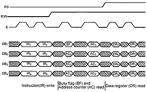
The LCD panel is connected to pins on PORTB. To communicate with the LCD we have to implement a protocol which involves changing the state of the control pins in a particular way. Hardware in the LCD will detect these operations and respond to them. The LCD data sheets give us timing diagrams which tell us how the signals are to change for the controller to react.
If you ever attach another device to a PICmicro you will almost certainly find that you have to use a similar set of signals in a particular sequence to interact with it. For this reason it is worth spending some time looking at the low level issues involved.
On the right you can see the timing diagram for our conversation with the LCD. We are using the LCD in four wire mode. Although all the commands and data are all eight bit values the LCD is able to respond to them if they are sent as two four bit values rather than a single eight bit one. This is done to save pins. Sending data four bits at a time is slower, and requires slightly more complex code, but since the LCD is a very slow device the tradeoff is worth making.
On the right hand side you can see the timing diagram for the LCD interface. This shows all the signals which are involved in the transaction and the points at which they change. The signals are as follows:
Data
There are 4 data signals between the PICmicro and the LCD. These can be used to send data in either direction, to or from the PICmicro. In the case of our use of the LCD we will only ever write values to the LCD, so they are always outputs from the PICmicro to the LCD.
In the PICmicro development board the data bits 0-3 of PORTB are connected to bits 4-7 of the data bits on the LCD. These bits must be configured as outputs
RS
The LCD can be given instructions (for example clear screen) or text (as ASCII characters). The RS signal is how the PICmicro can tell the LCD whether the data being exchanged is an instruction or a data item. If the signal is set low this means that we are moving instructions around. If the signal is high we are transferring data.
In the timing diagram on the right we are transferring a command for the first two transactions, and data for the third.
On the PICmicro development board the RS line on the LCD is connected to bit 4 of PORTB.
R/W
The LCD can be written to or read from. The PICmicro sends instructions and data to the LCD and it can return status information. The R/W (read write) signal lets us tell the LCD whether we wish to read or write. If the signal is low this means that the PICmicro wishes to tell the LCD something. If the R/W signal is high this means that the PICmicro is trying to read something from the LCD.
In the timing diagram the first transition is a write, followed by two read operations.
For simplicity's sake the PICmicro development board connection wires the LCD R/W line permanently low. This means that there is no way to read from the LCD, but this is not a problem in practice.
E
The E (enable) signal is how we clock data into the LCD panel. The LCD is sensitive to transitions (changes) in this signal, in particular changes from high to low. When the LCD sees one of these it looks at the data, R/W and RS lines to decide what is going on. If the LCD has been set to 4 wire mode it will require two such transitions to transfer a single byte command.
In the timing diagram you can see the E signal going up and down as the data is transferred.
On the PICmicro development board the E signal on the LCD is connected to bit 5 of PORTB.
Sending Messages
To send a message to the LCD we must do the following:
-
Set up the information to be transferred on bits 0-3 of PORTB
-
Set up RS to indicate whether we are sending data or instructions
-
Lift the E signal
-
Drop the E signal
-
Wait for the LCD to complete the command
Note that the speed at which E changes is not a problem, but we must make sure that the LCD has finished one command before sending the next. The LCD data sheet gives us maximum command timings so that we can wait for a commands to complete. If we are very concerned about speed we would read back the busy information from the LCD panel so that we know the instant the command has completed.
