|
Introduction to Microcontroller Programming * Course Index * Introduction * About the Author * About this Course * Feedback * Course Navigation * Quick Course Navigation * How to use this Course * Acronyms Used and Course Conventions About PICmicro Chips * What is a PICmicro? * Microcontrollers * Digital versus Analogue * Inputs and Outputs * Memory * Programming * 16F1937 Architecture Clocking Your PICmicro Devices * Introduction * The Clock Circuit * Clock Settings * Clock Confusion E-Blocks * Introduction to E-blocks * Using E-blocks * E-blocks Boards Flowcode Step By Step * Introduction to Flowcode * Basic Flowcode Functions * Digital Outputs * Digital Inputs * Basic Loops * The LCD Display * Binary Numbers * Decisions * Goto (Connection Point) * 7-Segment Displays * Software Macro * Strings and Memory * A Simple Hi-Fi PICmicro Projects * Introduction to PICmicro Projects * Construction Methods * Choosing a Power Source * Adding Inputs * Input Conditioning * Adding Outputs * Adding Drivers Labs * Introduction and Lesson Plan * 1. Output * 2. Delay * 3. Connection Point * 4. Calculations * 5. Loop * 6. Input * 7. Decision * 8. LCD * 9. Keypad * 10. Analogue + EEPROM * 11. Software Macro * 12. External Interrupt * 13. Timer Interrupt |
(:Summary:Contains the 'action' links (like Browse, Edit, History, etc.), placed at the top of the page, see site page actions:) (:comment This page can be somewhat complex to figure out the first time you see it. Its contents are documented at PmWiki.SitePageActions if you need help. :) * Print (:comment (:if group Site,SiteAdmin,Cookbook,Profiles,PmWiki*:) (:comment delete if and ifend to enable backlinks:) * %item rel=nofollow class=backlinks accesskey='$[ak_backlinks]'% [[{*$Name}?action=search&q=link={*$FullName} | $[Backlinks] ]] (:ifend:) :) * Login Labs /
Lab 2 - Delay<^< 1. Output | Course Index | 3. Connection Point >^>(:nl:) ->'''''1. Introduction''''' Microcontrollers are extremely fast. A PIC that is clocked with an Xtal of 20MHz will execute about 5,000,000 assembly instructions, every second. To let the PIC communicate with ‘slow’ humans, we will need to slow it down at certain times. This is done by adding a Delay instruction. ->'''''2. Setting up the equipment''''' 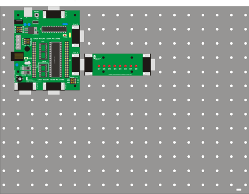 ->'''''3. Hardware settings'''''
->'''''4. Flowcode and download settings'''''
->'''''5. Software learning objectives''''' Output, Delay, Timing, binary code training, compiling a program to the PIC, clocking the PIC, PIC microcontroller basics. ->'''''6. Hardware learning objectives''''' LED’s, logic output levels, Multiprogrammer basics, speed of a microcontroller, time measurement with an oscilloscope. ->'''''7. Instructions''''' Construct the system shown from E-blocks. In the course navigate to the ‘Flowcode step-by-step’ and review the section on Basic Loops (step 4) and Decisions (step 7). In the course you will also find the sections on Clocking your PIC, and about PIC microcontroller basics useful. The descriptions of the multiprogrammer board and the led board are in the E-blocks section. Also make use of the Help-function in Flowcode to get the info you need. During these exercises you are going to send different 8-bit codes to port B of your Microcontroller. You'll learn how delays are used to slow the PIC down. Keep aware that your PIC microcontroller executes approximately at 5,000,000 assembly instructions per second and that the human eye in combination with the brain can only detect and understand approximately 3 stable images per second. ->'''''8. Labs'''''
:L2-B1: Open the program [L1-B9] that you wrote in LAB 1 use 'Delay' instructions between the 20 different output instructions to visualise these different outputs, even at HS Xtal speeds. Download the program to the PIC that is clocked by the Xtal. :L2-B2: In the exercise above: start with a delay of 1 sec and make the delay shorter, step by step until the point that it gets too fast for your eyes to detect 2 different LED outputs. Do not test this in simulation mode. The timing in simulation mode is not always correct because it runs under a Windows operating system and this is not ‘real time’. Download the program to the PIC every time you change the delay and test it on the actual E-blocks. :L2-B3: Light LEDs 0-7 one by one, turn them all off and then back on. Use delays to make it all viewable on the actual E-blocks. Clocking of the PIC is done by an Xtal of 19,660,800Hz. :L2-I4: If you have an oscilloscope, use it to measure if the delays you have set up in Flowcode are correct. Make a detailed drawing of the oscilloscope image you see and add correct voltage and timing information to it. Make a note on it what delay-time you used in your Flowcode program. (:nl:)(:table style="clear:both":)
| |
(:Summary: Website page footer:)
Print - (:comment (:if group Site,SiteAdmin,Cookbook,Profiles,PmWiki*:) (:comment delete if and ifend to enable backlinks:) %item rel=nofollow class=backlinks accesskey='$[ak_backlinks]'% [[{*$Name}?action=search&q=link={*$FullName} | $[Backlinks] ]] (:ifend:) :) Search - Login
Page last modified on May 14, 2013, at 01:50 PM