|
Introduction to Microcontroller Programming * Course Index * Introduction * About the Author * About this Course * Feedback * Course Navigation * Quick Course Navigation * How to use this Course * Acronyms Used and Course Conventions About PICmicro Chips * What is a PICmicro? * Microcontrollers * Digital versus Analogue * Inputs and Outputs * Memory * Programming * 16F1937 Architecture Clocking Your PICmicro Devices * Introduction * The Clock Circuit * Clock Settings * Clock Confusion E-Blocks * Introduction to E-blocks * Using E-blocks * E-blocks Boards Flowcode Step By Step * Introduction to Flowcode * Basic Flowcode Functions * Digital Outputs * Digital Inputs * Basic Loops * The LCD Display * Binary Numbers * Decisions * Goto (Connection Point) * 7-Segment Displays * Software Macro * Strings and Memory * A Simple Hi-Fi PICmicro Projects * Introduction to PICmicro Projects * Construction Methods * Choosing a Power Source * Adding Inputs * Input Conditioning * Adding Outputs * Adding Drivers Labs * Introduction and Lesson Plan * 1. Output * 2. Delay * 3. Connection Point * 4. Calculations * 5. Loop * 6. Input * 7. Decision * 8. LCD * 9. Keypad * 10. Analogue + EEPROM * 11. Software Macro * 12. External Interrupt * 13. Timer Interrupt |
(:Summary:Contains the 'action' links (like Browse, Edit, History, etc.), placed at the top of the page, see site page actions:) (:comment This page can be somewhat complex to figure out the first time you see it. Its contents are documented at PmWiki.SitePageActions if you need help. :) * Print (:comment (:if group Site,SiteAdmin,Cookbook,Profiles,PmWiki*:) (:comment delete if and ifend to enable backlinks:) * %item rel=nofollow class=backlinks accesskey='$[ak_backlinks]'% [[{*$Name}?action=search&q=link={*$FullName} | $[Backlinks] ]] (:ifend:) :) * Login Labs /
Lab 9 - Keypad<^< 8. LCD | Course Index | 10. Analogue + EEPROM >^>(:nl:) ->'''''1. Introduction''''' A numeric keypad is used in many electronic devices. The most commonly used is probably your cell phone where it is used both as a numeric keypad and as a way to type text instead of numbers. ->'''''2. Setting up the equipment''''' 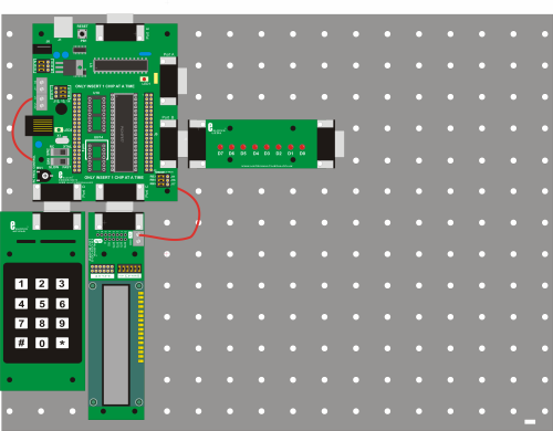 ->'''''3. Hardware settings'''''
->'''''4. Flowcode and download settings'''''
->'''''5. Software learning objectives''''' Input, output, binary code training, using a hardware macro (Keypad), working with text, working with the ASCII table, what a hardware macro is exactly? ->'''''6. Hardware learning objectives''''' LED’s, Logic output levels, LCD, How a numeric keypad works, Multiplexed inputs. ->'''''7. Instructions''''' Construct the system shown from E-blocks. In the course navigate to the ‘Flowcode step-by-step’ and review the section on The LCD Display (step 5) and the section on Strings and memory (step 11). The descriptions of the Multiprogrammer board , the keypad board, the LCD and the led board are in the E-blocks section. Look into the 'Help' menu and function in Flowcode to get the info you need. There are 12 buttons on the keypad and the keypad is connected to the PIC by only 8 lines. This problem is solved by using multiplexing. ->'''''8. Labs'''''
:L9-B1: Display the number that is pressed on the Keypad, on the LCD. Leave it on the LCD for as long as the button on the keypad is pressed. The LCD should only show one number at a time. Download this program to the PIC and test it. :L9-I2: Do the same task as in L9-B1, but now without using the Keypad hardware Macro. Download this program to the PIC and test it. :L9-B3: Display the numbers that are pressed on the Keypad, on the LCD, one after the other. Use the character * for a space and when # is pressed, the LCD should be cleared. Limit the maximum number of characters on the LCD to 15. Display a warning text on line 2 of the LCD when this number gets exceeded. Download this program to the PIC and test it. :L9-E4: Make a simple adding calculator with the Keypad and the LCD. The 2 numbers that are added can not be greater than 9999. Display an error message on line 2 if this occurs. * should be used for ‘+’ and # should be used for ‘=’. The 2 numbers, the ‘+’, the ‘=’ and the result should be displayed all together on line one of the LCD. Download this program to the PIC and test it. :L9-B5: Make a simple game where a player needs to guess a number between 0 and 9. The secret number is pre-programmed in the PIC. If the guessed number isn’t correct, then the LCD displays a message on line 2 with the info if the secret number is bigger or smaller than the number guessed by the player. Use * and # as you want to make this game. The keypad should be used as an input device for the numbers, the LCD should be used as the output device. Line 1 of the LCD should display the last input of the Keypad. Download this program to the PIC and test it. :L9-I6: Make a more complex game where a player needs to guess a number between 0 and 255. The secret number is pre-programmed. If the guessed number isn’t correct, then the LCD should display a message on line 2 with the info if the secret number is bigger or smaller than the number guessed by the player. Use * and # as you want to make this game. The keypad is used as an input device for the numbers, the LCD is the output device. Line one of the LCD should display the last input of the Keypad. Download this program to the PIC and test it. :L9-I7: Make an even more complex game where a player needs to guess a number between 0 and 9999. The secret number is pre-programmed. If the guessed number isn’t correct, then the LCD displays a message on line 2 with the info if the secret number is bigger or smaller than the number guessed by the player. Use * and # as you want, to make this game. The keypad is used as an input device for the numbers, the LCD is the output device. Line 1 of the LCD should display the last input of the Keypad. Download this program to the PIC and test it. :L9-E8: Use the keypad as it is used on your cell phone to input a text to the PIC. This text is shown on the LCD. * stands for a space and when # is pressed, the LCD needs to be cleared. Make use of the ASCII table to do this task. A text message can not be longer that 10 characters. Display a warning text on line 2 of the LCD when this number gets exceeded. Download this program to the PIC and test it. :L9-I9: Draw up the full circuit diagram of the PIC with 8 LEDs on port B, the LCD on port C and the Keypad on port D, including the clocking circuit, the reset circuit, VDD and VSS connected to the PIC and the correct current limiting resistors connected between LEDs and the PIC. If you were to make a practical circuit of this drawing, and connect power to it, it should behave exactly the same as the e-blocks system in front of you. Schematics in the E-blocks section and the full circuit diagrams in the datasheets of the E-blocks will come in handy when you do this task. (:nl:)(:table style="clear:both":)
| |
(:Summary: Website page footer:)
Print - (:comment (:if group Site,SiteAdmin,Cookbook,Profiles,PmWiki*:) (:comment delete if and ifend to enable backlinks:) %item rel=nofollow class=backlinks accesskey='$[ak_backlinks]'% [[{*$Name}?action=search&q=link={*$FullName} | $[Backlinks] ]] (:ifend:) :) Search - Login
Page last modified on May 13, 2013, at 03:36 PM