|
Electronic circuits and components * Course Index * Introduction * About the Author * About this Course * Feedback * Course Navigation * How to use this Course * TINA * Locktronics Fundamentals * Introduction: Fundamentals * Units and Multiples * Electricity * Electronic Principles * Electrical Circuits * Alternating Current * Assessment: Fundamentals Passive Components * Introduction: Passive Components * Resistors ## Resistor Specifications ## Examples: Resistor Specifications ## Preferred Values: Resistors ## Resistor Colour Code ## Examples: Resistor Colour Code Test ## BS1852 Resistor Coding ## Examples: BS1852 Resistor Coding ## Measuring Resistance ## Resistor Symbols ## Resistor Construction ## Resistors in Series ## Worksheet: Resistors in Series ## Resistors in Parallel ## Worksheet: Resistors in Parallel ## Resistance and Temperature ## Examples: Resistance and Temperature ## Positive Temperature Coefficient ## Negative Temperature Coefficient ## Thermistors ## Light Dependent Resistors * Capacitors * Inductors * Transformers * Batteries, Fuses, Lamps and Switches * Assessment: Passive Components Semiconductors * Introduction: Semiconductors * Diodes * Transistors * Logic Gates * Assessment: Semiconductors Passive Circuits * Introduction: Passive Circuits * Series and Parallel Connections * Kirchoff's Laws * Potential and Current Dividers * Passive Time Variant Circuits * Assessment: Passive Circuits Active Circuits * Introduction: Active Circuits * Power Supply Circuits * Operational Amplifier Circuits * Transistor Amplifier Circuits * 555 Timer Circuits * Assessment: Active Circuits Parts Gallery * Introduction: Parts Gallery * Passive Component Images * Semiconductor Images * Other Images * Quizzes |
(:Summary:Contains the 'action' links (like Browse, Edit, History, etc.), placed at the top of the page, see site page actions:) (:comment This page can be somewhat complex to figure out the first time you see it. Its contents are documented at PmWiki.SitePageActions if you need help. :) * Print (:comment (:if group Site,SiteAdmin,Cookbook,Profiles,PmWiki*:) (:comment delete if and ifend to enable backlinks:) * %item rel=nofollow class=backlinks accesskey='$[ak_backlinks]'% [[{*$Name}?action=search&q=link={*$FullName} | $[Backlinks] ]] (:ifend:) :) * Login Thermistors<^< Negative Temperature Coefficient | Course Index | Light Dependent Resistors >^>(:nl:) 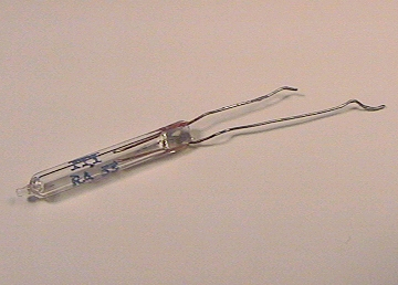 With conventional resistors we would normally require resistance to remain the same over a wide range of temperatures (i.e., α should be zero). On the other hand, there are applications in which we could use the effect of varying resistance to detect a temperature change. Components that allow us to do this are known as thermistors. The resistance of a thermistor changes markedly with temperature and these components are widely used in temperature sensing and temperature compensating applications. Two basic types of thermistor are available, according to whether their resistance increases or decreases with temperature. These are respectively known as positive temperature coefficient (PTC) and negative temperature coefficient (NTC). Typical NTC thermistors have resistance's which vary from a few hundred (or thousand) ohms at 25°C to a few tens (or hundreds) of ohms at 100°C. PTC thermistors, on the other hand, usually have a resistance-temperature characteristic which remains substantially flat (typically at around 100Ω) over the range 0°C to around 75°C. Above this, and at a critical temperature (usually in the range 80°C to 120°C) their resistance rises very rapidly to values of up to, and beyond, 10kΩ. A typical application of PTC thermistors is over-current protection. Provided the current passing through the thermistor remains below the threshold current, the effects of self heating will remain negligible and the resistance of the thermistor will remain low (i.e., approximately the same as the resistance quoted at 25°C). Under fault conditions, the current exceeds the threshold value by a considerable margin and the thermistor starts to self-heat. The resistance then increases rapidly and, as a consequence, the current falls to the rest value. Typical values of threshold and rest currents are 200mA and 8mA respectively for a device which exhibits a nominal resistance of 25Ω at 25°C. (:nl:)(:table style="clear:both":)
| |
(:Summary: Website page footer:)
Print - (:comment (:if group Site,SiteAdmin,Cookbook,Profiles,PmWiki*:) (:comment delete if and ifend to enable backlinks:) %item rel=nofollow class=backlinks accesskey='$[ak_backlinks]'% [[{*$Name}?action=search&q=link={*$FullName} | $[Backlinks] ]] (:ifend:) :) Search - Login
Page last modified on August 15, 2011, at 02:42 PM