|
Introduction to Microcontroller Programming * Course Index * Introduction * About the Author * About this Course * Feedback * Course Navigation * Quick Course Navigation * How to use this Course * Acronyms Used and Course Conventions About PICmicro Chips * What is a PICmicro? * Microcontrollers * Digital versus Analogue * Inputs and Outputs * Memory * Programming * 16F1937 Architecture Clocking Your PICmicro Devices * Introduction * The Clock Circuit * Clock Settings * Clock Confusion E-Blocks * Introduction to E-blocks * Using E-blocks * E-blocks Boards Flowcode Step By Step * Introduction to Flowcode * Basic Flowcode Functions * Digital Outputs * Digital Inputs ## Set up the Equipment ## Equivalent Circuit ## Where's the Fire? ## Set up the Flowchart ## Variables ## Using Variables ## Set up the Outputs ## Adding the Switches * Basic Loops * The LCD Display * Binary Numbers * Decisions * Goto (Connection Point) * 7-Segment Displays * Software Macro * Strings and Memory * A Simple Hi-Fi PICmicro Projects * Introduction to PICmicro Projects * Construction Methods * Choosing a Power Source * Adding Inputs * Input Conditioning * Adding Outputs * Adding Drivers Labs * Introduction and Lesson Plan * 1. Output * 2. Delay * 3. Connection Point * 4. Calculations * 5. Loop * 6. Input * 7. Decision * 8. LCD * 9. Keypad * 10. Analogue + EEPROM * 11. Software Macro * 12. External Interrupt * 13. Timer Interrupt |
(:Summary:Contains the 'action' links (like Browse, Edit, History, etc.), placed at the top of the page, see site page actions:) (:comment This page can be somewhat complex to figure out the first time you see it. Its contents are documented at PmWiki.SitePageActions if you need help. :) * Print (:comment (:if group Site,SiteAdmin,Cookbook,Profiles,PmWiki*:) (:comment delete if and ifend to enable backlinks:) * %item rel=nofollow class=backlinks accesskey='$[ak_backlinks]'% [[{*$Name}?action=search&q=link={*$FullName} | $[Backlinks] ]] (:ifend:) :) * Login Set up the Outputs<^< Using Variables | Course Index | Adding the Switches >^>(:nl:) # Next, right-click on the Output icon, and select 'Properties' or just simply double-click the Output icon. The Output Properties box appears. # Click on the # Double-click on the word 'SENSOR' or click and drag it to the variable box. # You are now back on the Output Properties box, which shows that the system is set to output whatever data is stored in the 'SENSOR' variable. Change the port used to Port B, by clicking on the # Click on OK to close the Output Properties box. # The flowchart should now look like this: 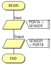 ->Notice the arrows in front of the 'PORTA' and 'PORTB' labels, they show that information will flow from Port A into the flowchart and will flow from the flowchart out to Port B. # Now click on the Outputs button and select LED Array #Change the 'Count' property under the 'Simulation' section to the value '5' by clicking on the box next to the property and using the keyboard to input the value. # Click next to the word 'Port' under the 'Connections' section in the Properties pane whilst the component is selected to open an interactive view of the chip which shows compatible pins. # Click on the drop-down menu and select the 'PORT B' option. You have now connected the LED's to the pins on Port B.(:nl:)(:table style="clear:both":)
| |
(:Summary: Website page footer:)
Print - (:comment (:if group Site,SiteAdmin,Cookbook,Profiles,PmWiki*:) (:comment delete if and ifend to enable backlinks:) %item rel=nofollow class=backlinks accesskey='$[ak_backlinks]'% [[{*$Name}?action=search&q=link={*$FullName} | $[Backlinks] ]] (:ifend:) :) Search - Login
Page last modified on July 22, 2013, at 09:11 AM
 button next to the variable box. You will see the 'SENSOR' variable listed.
 icon. Place the LED Array where you want it on the panel by clicking and dragging it with the mouse cursor.