|
Introduction to Microcontroller Programming * Course Index * Introduction * About the Author * About this Course * Feedback * Course Navigation * Quick Course Navigation * How to use this Course * Acronyms Used and Course Conventions About PICmicro Chips * What is a PICmicro? * Microcontrollers * Digital versus Analogue * Inputs and Outputs * Memory * Programming * 16F1937 Architecture Clocking Your PICmicro Devices * Introduction * The Clock Circuit * Clock Settings * Clock Confusion E-Blocks * Introduction to E-blocks * Using E-blocks * E-blocks Boards Flowcode Step By Step * Introduction to Flowcode * Basic Flowcode Functions * Digital Outputs * Digital Inputs * Basic Loops * The LCD Display * Binary Numbers * Decisions * Goto (Connection Point) * 7-Segment Displays * Software Macro * Strings and Memory * A Simple Hi-Fi PICmicro Projects * Introduction to PICmicro Projects * Construction Methods ## Building Circuits with PICmicro's ## Prototype Board ## E-blocks Prototyping Boards ## Stripboard ## Printed Circuit Board * Choosing a Power Source * Adding Inputs * Input Conditioning * Adding Outputs * Adding Drivers Labs * Introduction and Lesson Plan * 1. Output * 2. Delay * 3. Connection Point * 4. Calculations * 5. Loop * 6. Input * 7. Decision * 8. LCD * 9. Keypad * 10. Analogue + EEPROM * 11. Software Macro * 12. External Interrupt * 13. Timer Interrupt |
(:Summary:Contains the 'action' links (like Browse, Edit, History, etc.), placed at the top of the page, see site page actions:) (:comment This page can be somewhat complex to figure out the first time you see it. Its contents are documented at PmWiki.SitePageActions if you need help. :) * Print (:comment (:if group Site,SiteAdmin,Cookbook,Profiles,PmWiki*:) (:comment delete if and ifend to enable backlinks:) * %item rel=nofollow class=backlinks accesskey='$[ak_backlinks]'% [[{*$Name}?action=search&q=link={*$FullName} | $[Backlinks] ]] (:ifend:) :) * Login Printed Circuit Board<^< Stripboard | Course Index | Choosing a Power Source >^>(:nl:) This starts life as a sheet of copper, stuck to an insulating board. Areas of the copper are removed, usually by chemical etching, to leave a pattern of copper strips and pads which form the connecting paths (wires) for the circuit. The board is then drilled, so that components can be mounted on the insulating board, with their legs pushed through the holes. These can then be soldered to the copper tracks on the other side. 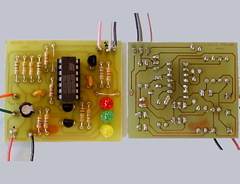 Advantages* mechanically robust - a permanent circuit; * allows 'mass production', when photographic techniques are used to mark out the areas of copper to remove * software packages are available to convert the circuit diagram into a PCB layout * usually produces the most compact arrangement for a given circuit Disadvantages* considerable processing needed to convert the initial blank baseboard into the final design * health and safety precautions needed when soldering, and when using chemicals to etch the copper * most components cannot be re-used * overall, the most expensive way to produce a 'one-off' circuit (:nl:)(:table style="clear:both":)
| |
(:Summary: Website page footer:)
Print - (:comment (:if group Site,SiteAdmin,Cookbook,Profiles,PmWiki*:) (:comment delete if and ifend to enable backlinks:) %item rel=nofollow class=backlinks accesskey='$[ak_backlinks]'% [[{*$Name}?action=search&q=link={*$FullName} | $[Backlinks] ]] (:ifend:) :) Search - Login
Page last modified on August 25, 2011, at 04:00 PM