|
Introduction to Microcontroller Programming * Course Index * Introduction * About the Author * About this Course * Feedback * Course Navigation * Quick Course Navigation * How to use this Course * Acronyms Used and Course Conventions About PICmicro Chips * What is a PICmicro? * Microcontrollers * Digital versus Analogue * Inputs and Outputs * Memory * Programming * 16F1937 Architecture Clocking Your PICmicro Devices * Introduction * The Clock Circuit * Clock Settings * Clock Confusion E-Blocks * Introduction to E-blocks * Using E-blocks * E-blocks Boards Flowcode Step By Step * Introduction to Flowcode * Basic Flowcode Functions * Digital Outputs * Digital Inputs * Basic Loops * The LCD Display * Binary Numbers * Decisions * Goto (Connection Point) * 7-Segment Displays * Software Macro * Strings and Memory * A Simple Hi-Fi PICmicro Projects * Introduction to PICmicro Projects * Construction Methods ## Building Circuits with PICmicro's ## Prototype Board ## E-blocks Prototyping Boards ## Stripboard ## Printed Circuit Board * Choosing a Power Source * Adding Inputs * Input Conditioning * Adding Outputs * Adding Drivers Labs * Introduction and Lesson Plan * 1. Output * 2. Delay * 3. Connection Point * 4. Calculations * 5. Loop * 6. Input * 7. Decision * 8. LCD * 9. Keypad * 10. Analogue + EEPROM * 11. Software Macro * 12. External Interrupt * 13. Timer Interrupt |
(:Summary:Contains the 'action' links (like Browse, Edit, History, etc.), placed at the top of the page, see site page actions:) (:comment This page can be somewhat complex to figure out the first time you see it. Its contents are documented at PmWiki.SitePageActions if you need help. :) * Print (:comment (:if group Site,SiteAdmin,Cookbook,Profiles,PmWiki*:) (:comment delete if and ifend to enable backlinks:) * %item rel=nofollow class=backlinks accesskey='$[ak_backlinks]'% [[{*$Name}?action=search&q=link={*$FullName} | $[Backlinks] ]] (:ifend:) :) * Login Stripboard<^< E-blocks Prototyping Boards | Course Index | Printed Circuit Board >^>(:nl:) Stripboard consists of parallel copper strips, stuck to an insulating baseboard. Each strip has a series of holes drilled though it. To build a circuit, each component is positioned on the insulating board, with its legs pushed through appropriate holes. On the copper strip side of the board, each leg is then soldered to the copper strip. In this way, the leg is in electrical contact with anything else soldered to the same strip. The photograph shows a circuit built on stripboard. The left hand image gives the view of the insulating baseboard side, with the components and any additional wiring needed. The right hand image shows the copper track side of the board. 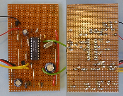 Image courtesy of Max Horsey. Advantages* mechanically robust - a permanent circuit * ready made baseboard. Disadvantages* health and safety precautions needed when soldering * most components cannot be re-used * difficult to create a compact layout * final component layout can be difficult to relate to the circuit diagram. (:nl:)(:table style="clear:both":)
| |
(:Summary: Website page footer:)
Print - (:comment (:if group Site,SiteAdmin,Cookbook,Profiles,PmWiki*:) (:comment delete if and ifend to enable backlinks:) %item rel=nofollow class=backlinks accesskey='$[ak_backlinks]'% [[{*$Name}?action=search&q=link={*$FullName} | $[Backlinks] ]] (:ifend:) :) Search - Login
Page last modified on August 25, 2011, at 03:57 PM