|
Introduction to Microcontroller Programming * Course Index * Introduction * About the Author * About this Course * Feedback * Course Navigation * Quick Course Navigation * How to use this Course * Acronyms Used and Course Conventions About PICmicro Chips * What is a PICmicro? * Microcontrollers * Digital versus Analogue * Inputs and Outputs * Memory * Programming * 16F1937 Architecture Clocking Your PICmicro Devices * Introduction * The Clock Circuit * Clock Settings * Clock Confusion E-Blocks * Introduction to E-blocks * Using E-blocks * E-blocks Boards Flowcode Step By Step * Introduction to Flowcode * Basic Flowcode Functions * Digital Outputs * Digital Inputs * Basic Loops * The LCD Display * Binary Numbers * Decisions * Goto (Connection Point) * 7-Segment Displays * Software Macro * Strings and Memory * A Simple Hi-Fi ## Introduction ## Set up the Equipment ## Port B Interrupts ## Setting up the LCD ## Using the ADC ## Finishing Touches PICmicro Projects * Introduction to PICmicro Projects * Construction Methods * Choosing a Power Source * Adding Inputs * Input Conditioning * Adding Outputs * Adding Drivers Labs * Introduction and Lesson Plan * 1. Output * 2. Delay * 3. Connection Point * 4. Calculations * 5. Loop * 6. Input * 7. Decision * 8. LCD * 9. Keypad * 10. Analogue + EEPROM * 11. Software Macro * 12. External Interrupt * 13. Timer Interrupt |
(:Summary:Contains the 'action' links (like Browse, Edit, History, etc.), placed at the top of the page, see site page actions:) (:comment This page can be somewhat complex to figure out the first time you see it. Its contents are documented at PmWiki.SitePageActions if you need help. :) * Print (:comment (:if group Site,SiteAdmin,Cookbook,Profiles,PmWiki*:) (:comment delete if and ifend to enable backlinks:) * %item rel=nofollow class=backlinks accesskey='$[ak_backlinks]'% [[{*$Name}?action=search&q=link={*$FullName} | $[Backlinks] ]] (:ifend:) :) * Login Port B Interrupts<^< Set up the Equipment | Course Index | Setting up the LCD >^>(:nl:) 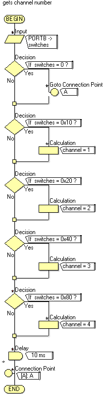 There are two more common interrupts that you should understand: Port B bit 0, and Port B change. The Port B bit 0 interrupt will trigger a given macro every time the RB0 line on the PICmicro device goes to a logic 1 or 5V. The Port B change interrupt triggers every time there is a change of state on the highest 4 bits of Port B: bits RB4, 5, 6, 7. The Port B bit 0 interrupt is straight forward enough, but the Port B change is a little more difficult to handle. Here we will set up part of a Hi-Fi system that has 4 preset radio channels - channels 1 to 4. Each one is selected by the use of one of 4 push-to-make switches connected to Port B. The idea behind our system will be that every time a switch is pressed the Port B change interrupt will trigger a macro that alters the channel number. Follow the instructions below to set up the program. # Start a new flowchart with a 16F1937 device. # Add an Interrupt icon to the program # Add a Loop to the program. Don't put anything in the loop yet. To start with the loop will just keep the program going: the real work will be done by the Interrupt routine we will make. # Add 4 push to make switches connected to pins B4, 5, 6, 7. Label them '1' to '4' # Add two new Byte variables: 'channel' and 'switches' # Add a new macro called 'Chandet' # Assemble the program shown to the right in the 'Chandet' macro. # Double-click on the Interrupt icon in the main program. In the 'Interrupt on:' box select 'PORT'. In the 'Will call macro:' box select 'Chandet' so that it will call the macro called 'Chandet'. # Select 'Build' then click 'Project Options' (Build > Project Options) and set simulation speed to '1000'. The actual value is not important: a setting other than 'As fast as possible' will allow you to see the values of the variables in the system as your program simulates. # Run the program, and check that the variable 'channel' is assigned a channel number on the press of a switch. Here is an explanation of how the 'Chandet' macro works: The first icon assigns the value of the top 4 bits of Port B to the variable switches. Use masking here to get the state of only the top 4 bits. The difficulty (or advantage) of the Port B change interrupt is that it triggers on a change of status in Port B. That means that it triggers when the switch is pressed, and also when it is released. Because of this you need to filter out all switch releases: we want to detect only switch presses. The first Decision box detects a value of 0 for the variable switches. If a 0 is detected the connection point diverts the program to the end of the Interrupt macro. The next Decision box detects a value of 0x10 (16 decimal). This corresponds to the switch on RB4 being pressed. If RB4 is pressed then we assign the variable 'channel' to have a value of 1. The next Decision box detects a value of 0x20 (32 decimal). This corresponds to the switch on RB5 being pressed. If RB5 is pressed then we assign the variable 'channel' to have a value of 2. You should now be able to work out how the complete program works. (:nl:)(:table style="clear:both":)
| |
(:Summary: Website page footer:)
Print - (:comment (:if group Site,SiteAdmin,Cookbook,Profiles,PmWiki*:) (:comment delete if and ifend to enable backlinks:) %item rel=nofollow class=backlinks accesskey='$[ak_backlinks]'% [[{*$Name}?action=search&q=link={*$FullName} | $[Backlinks] ]] (:ifend:) :) Search - Login
Page last modified on May 03, 2013, at 02:39 PM