|
Introduction to Microcontroller Programming * Course Index * Introduction * About the Author * About this Course * Feedback * Course Navigation * Quick Course Navigation * How to use this Course * Acronyms Used and Course Conventions About PICmicro Chips * What is a PICmicro? * Microcontrollers * Digital versus Analogue * Inputs and Outputs * Memory * Programming * 16F1937 Architecture Clocking Your PICmicro Devices * Introduction * The Clock Circuit * Clock Settings * Clock Confusion E-Blocks * Introduction to E-blocks * Using E-blocks ## About E-blocks ## E-blocks Projects ## How E-blocks Connect to Each Other ## Physical Properties of E-blocks ## Using a Backplane ## Protecting E-blocks Circuitry ## Using Covers ## Adding Power to E-blocks ## Understanding the Patch System ## Sharing a Port ## Using ZIF Sockets * E-blocks Boards Flowcode Step By Step * Introduction to Flowcode * Basic Flowcode Functions * Digital Outputs * Digital Inputs * Basic Loops * The LCD Display * Binary Numbers * Decisions * Goto (Connection Point) * 7-Segment Displays * Software Macro * Strings and Memory * A Simple Hi-Fi PICmicro Projects * Introduction to PICmicro Projects * Construction Methods * Choosing a Power Source * Adding Inputs * Input Conditioning * Adding Outputs * Adding Drivers Labs * Introduction and Lesson Plan * 1. Output * 2. Delay * 3. Connection Point * 4. Calculations * 5. Loop * 6. Input * 7. Decision * 8. LCD * 9. Keypad * 10. Analogue + EEPROM * 11. Software Macro * 12. External Interrupt * 13. Timer Interrupt |
(:Summary:Contains the 'action' links (like Browse, Edit, History, etc.), placed at the top of the page, see site page actions:) (:comment This page can be somewhat complex to figure out the first time you see it. Its contents are documented at PmWiki.SitePageActions if you need help. :) * Print (:comment (:if group Site,SiteAdmin,Cookbook,Profiles,PmWiki*:) (:comment delete if and ifend to enable backlinks:) * %item rel=nofollow class=backlinks accesskey='$[ak_backlinks]'% [[{*$Name}?action=search&q=link={*$FullName} | $[Backlinks] ]] (:ifend:) :) * Login Adding Power to E-blocks<^< Using Covers | Course Index | Understanding the Patch System >^>(:nl:) Power connections are always routed separately between E-blocks using simple screw terminals. This facilitates the interoperation of E-blocks with different voltage levels (notably 3.3V and 5V) and power sources. Most upstream E-blocks have 5V outputs provided by a voltage regulator. These E-blocks are powered by applying a higher voltage via a power jack (usually positive outer) or using screw terminal blocks. As 0V is connected to all blocks through the 9 way D-type connectors it is only necessary to connect power to all E-blocks. Most upstream E-blocks have a regulator that produces 5V, and many downstream E-blocks have 5V loop through screw terminals which allow users to keep power wires tidy. To neaten up more permanent systems power wires can be looped under E-blocks and under the backplanes. On this photograph you can clearly see the red power wires linking the E-blocks together. This design routes 14V from the Multiprogrammer to the Proto board. Be careful when doing this as there is a chance you can damage the PICmicro microcontroller on your Multiprogrammer board if you get the connections wrong. 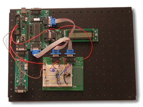 (:nl:)(:table style="clear:both":)
| |
(:Summary: Website page footer:)
Print - (:comment (:if group Site,SiteAdmin,Cookbook,Profiles,PmWiki*:) (:comment delete if and ifend to enable backlinks:) %item rel=nofollow class=backlinks accesskey='$[ak_backlinks]'% [[{*$Name}?action=search&q=link={*$FullName} | $[Backlinks] ]] (:ifend:) :) Search - Login
Page last modified on August 26, 2011, at 03:51 PM