|
Introduction to Microcontroller Programming * Course Index * Introduction * About the Author * About this Course * Feedback * Course Navigation * Quick Course Navigation * How to use this Course * Acronyms Used and Course Conventions About PICmicro Chips * What is a PICmicro? * Microcontrollers * Digital versus Analogue * Inputs and Outputs * Memory * Programming * 16F1937 Architecture Clocking Your PICmicro Devices * Introduction * The Clock Circuit * Clock Settings * Clock Confusion E-Blocks * Introduction to E-blocks * Using E-blocks * E-blocks Boards Flowcode Step By Step * Introduction to Flowcode * Basic Flowcode Functions * Digital Outputs * Digital Inputs * Basic Loops * The LCD Display * Binary Numbers * Decisions * Goto (Connection Point) * 7-Segment Displays * Software Macro * Strings and Memory * A Simple Hi-Fi PICmicro Projects * Introduction to PICmicro Projects * Construction Methods * Choosing a Power Source * Adding Inputs * Input Conditioning * Adding Outputs ## LED's ## Using LED's ## 7seg Displays ## LCD Displays ## Using LCD Displays ## Buzzers / Sounders ## Motors ## Stepper Motors ## Solenoids * Adding Drivers Labs * Introduction and Lesson Plan * 1. Output * 2. Delay * 3. Connection Point * 4. Calculations * 5. Loop * 6. Input * 7. Decision * 8. LCD * 9. Keypad * 10. Analogue + EEPROM * 11. Software Macro * 12. External Interrupt * 13. Timer Interrupt |
(:Summary:Contains the 'action' links (like Browse, Edit, History, etc.), placed at the top of the page, see site page actions:) (:comment This page can be somewhat complex to figure out the first time you see it. Its contents are documented at PmWiki.SitePageActions if you need help. :) * Print (:comment (:if group Site,SiteAdmin,Cookbook,Profiles,PmWiki*:) (:comment delete if and ifend to enable backlinks:) * %item rel=nofollow class=backlinks accesskey='$[ak_backlinks]'% [[{*$Name}?action=search&q=link={*$FullName} | $[Backlinks] ]] (:ifend:) :) * Login 7-Segment Displays<^< Using LED's | Course Index | LCD Displays >^>(:nl:) These consist of seven LED's arranged so that the numbers 0 to 9 can be displayed by lighting appropriate 'segments'. 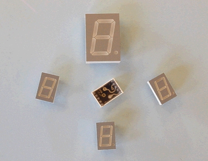 The next diagram illustrates how the number 3.57 can be displayed.  The pin arrangement of a typical 7-segment display is shown below.  The seven LED's, (eight if you count the decimal point,) are interconnected in one of two ways, known as common-anode and common-cathode format. In the common anode format, all the anodes are connected together inside the 7-segment display package. In use, they are then are connected to the positive power supply through a series protective resistor. Normally, the cathodes of all the LED's are held at logic 1. To make a segment light, the cathode of that led is connected to logic 0. This can be done by connecting the display directly to the outputs of a PICmicro chip, or by using a decoder/driver integrated circuit.  In the common cathode format, all the cathodes are connected together internally. In the circuit, they are connected to the negative supply (0V) through a series resistor. Normally, they are held at logic 0, but to light a segment, it is connected to logic 1.  (:nl:)(:table style="clear:both":)
| |
(:Summary: Website page footer:)
Print - (:comment (:if group Site,SiteAdmin,Cookbook,Profiles,PmWiki*:) (:comment delete if and ifend to enable backlinks:) %item rel=nofollow class=backlinks accesskey='$[ak_backlinks]'% [[{*$Name}?action=search&q=link={*$FullName} | $[Backlinks] ]] (:ifend:) :) Search - Login
Page last modified on August 26, 2011, at 10:03 AM