|
Introduction to Microcontroller Programming * Course Index * Introduction * About the Author * About this Course * Feedback * Course Navigation * Quick Course Navigation * How to use this Course * Acronyms Used and Course Conventions About PICmicro Chips * What is a PICmicro? * Microcontrollers * Digital versus Analogue * Inputs and Outputs * Memory * Programming * 16F1937 Architecture ## PORT A ## PORT B ## PORT C ## PORT D ## PORT E ## Memory in the 16F1937 ## ALU ## Timer 1 ## Timer 0 ## RB0 Interrupt ## Port B Interrupt ## Clocking Your PICmicro Devices * Introduction * The Clock Circuit * Clock Settings * Clock Confusion E-Blocks * Introduction to E-blocks * Using E-blocks * E-blocks Boards Flowcode Step By Step * Introduction to Flowcode * Basic Flowcode Functions * Digital Outputs * Digital Inputs * Basic Loops * The LCD Display * Binary Numbers * Decisions * Goto (Connection Point) * 7-Segment Displays * Software Macro * Strings and Memory * A Simple Hi-Fi PICmicro Projects * Introduction to PICmicro Projects * Construction Methods * Choosing a Power Source * Adding Inputs * Input Conditioning * Adding Outputs * Adding Drivers Labs * Introduction and Lesson Plan * 1. Output * 2. Delay * 3. Connection Point * 4. Calculations * 5. Loop * 6. Input * 7. Decision * 8. LCD * 9. Keypad * 10. Analogue + EEPROM * 11. Software Macro * 12. External Interrupt * 13. Timer Interrupt |
(:Summary:Contains the 'action' links (like Browse, Edit, History, etc.), placed at the top of the page, see site page actions:) (:comment This page can be somewhat complex to figure out the first time you see it. Its contents are documented at PmWiki.SitePageActions if you need help. :) * Print (:comment (:if group Site,SiteAdmin,Cookbook,Profiles,PmWiki*:) (:comment delete if and ifend to enable backlinks:) * %item rel=nofollow class=backlinks accesskey='$[ak_backlinks]'% [[{*$Name}?action=search&q=link={*$FullName} | $[Backlinks] ]] (:ifend:) :) * Login A / D Conversion<^< Port B Interrupt | Course Index | Busses >^>(:nl:) Largely simplified block schematic to demonstrate where the A/D Converter is located in the PIC 16F1937 Architecture: 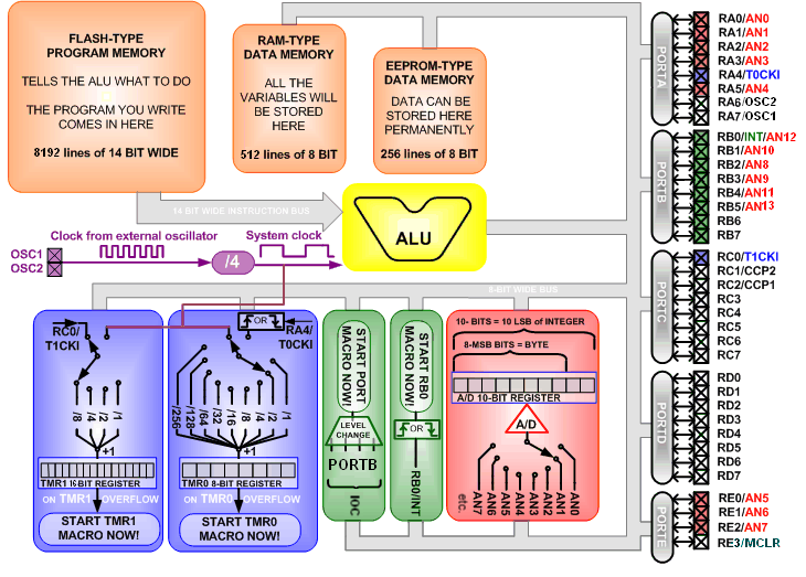 A / D:* This 16F1937 PICmicro microcontroller has 14 pins that have an extra A/D function. * This PICmicro controller has only one single 10-bit A/D converter. * This implies that these 14 analogue inputs can't all be read at the same time. * A built in analogue switch is the answer to this problem. * In Flowcode you can select which of the 14 analogue inputs you want to sample. * After this 'sample' instruction, the analogue switch is set to the correct input and this analogue input is converted to a 10-bit binary value. * In Flowcode, you can select to only use the 8 MSB's of this 10-bit value by using the 'GetByte' instruction, or you can select to use the full 10 bits by selecting the 'GetInt' instruction. The 10 bits will fill up the 10 LSB's of the selected 16-bit integer variable. * After this, you can select an other analogue input that needs to be read. (:nl:)(:table style="clear:both":)
| |
(:Summary: Website page footer:)
Print - (:comment (:if group Site,SiteAdmin,Cookbook,Profiles,PmWiki*:) (:comment delete if and ifend to enable backlinks:) %item rel=nofollow class=backlinks accesskey='$[ak_backlinks]'% [[{*$Name}?action=search&q=link={*$FullName} | $[Backlinks] ]] (:ifend:) :) Search - Login
Page last modified on May 13, 2013, at 02:54 PM